
Installation of the display module into the Fiero speedo is not as simple as for the F-body cluster. It requires not only to remove the speedometer from the cluster, but also to completely disassemble it!
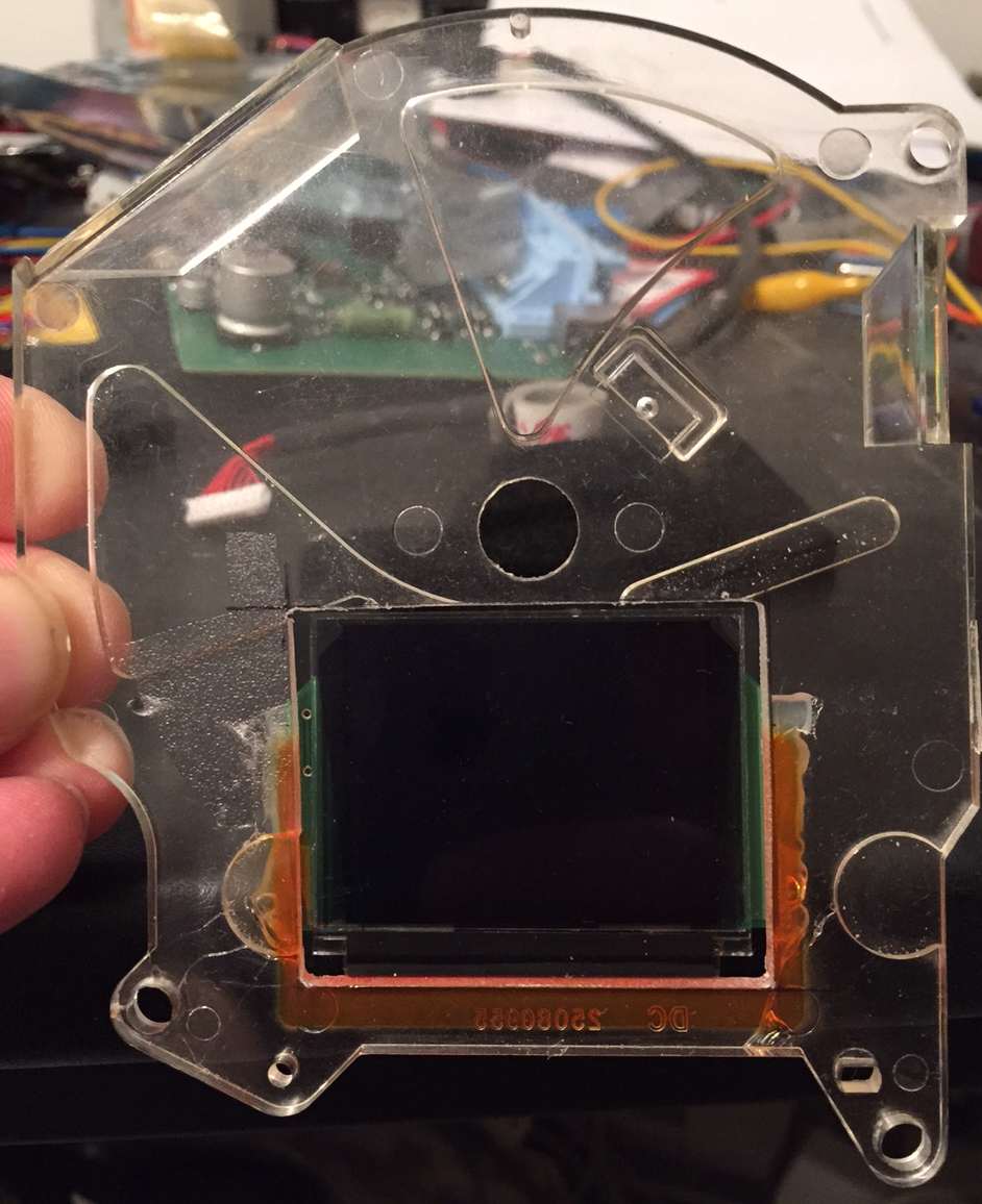
The indicator needle has to be pulled off carefully and the plexiglass carrier has to be separated from the faceplate and the support frame. Now a rectangular opening must be milled into the plexiglass, sacrificing one of the two air core motor positioning posts. Don't worry, it's not needed. The opening must be milled just large enough to accomodate the TFT or OLED module (about 43 x 34 mm). The module can't be moved up higher because then this would interfere with the air core motor, if it's moved lower, it is no longer completely visible when installed in the cluster.
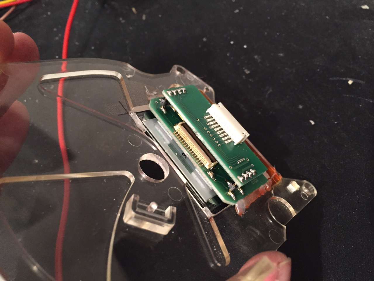
The display module can now be installed and aligned into the opening in the plexiglass and fixed with hot glue. This has the advantage of being able to correct the position later on, which is not the case if epoxy is used for installation. The carrier circuit board is slightly wider than the display to allow glueing it to the plexiglass.
Care must be taken not to get glue on the display glass, and the flexible circuit board is also very delicate and should not be bent or otherwise folded, so it's better to have a larger opening towards the bottom of the plexiglass to have some space for the flex board. This part of the speedometer will not be visible after installation anyway. Carefully push the small red display harness into the white connector on the TFT/OLED module and set aside the Plexiglass with display and wiring.
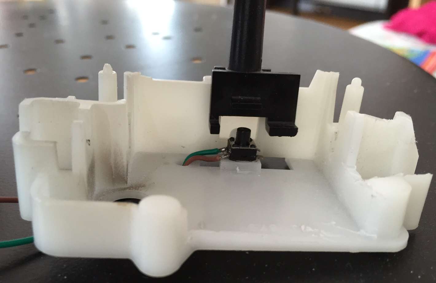
To operate DashComputer at least one switch is required, and it's a smart idea to use the now obsolete trip odometer stalk for this purpose. The trip odometer and drive gears need to be completely removed, and some parts cut off if they are interfering with the display board. Test fit things carefully and then cut away e.g. with a Dremel, use the image above for reference. Then a small microswitch must be glued (this time with epoxy!) as shown in the picture so that the actuator (the little flap) on the pushbutton operates the microswitch when it is pushed. A three wire pigtail is provided to connect up to two switches to the board. The center wire is common, the outer two are connected to the "trip reset" and "set clock/menu" switches. The "trip reset" switch is the one operated when you push the odometer stalk.
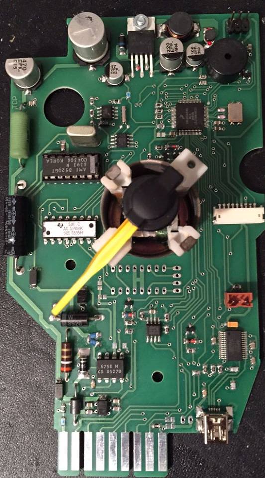
Now the new circuit board (below) is ready for assembly. Assemble the support frame with the board and air core motor, place plexiglass on top and plug the two connectors into the new circuit board (the small white display and even smaller switch connectors are at the right side of the board). Reinstall all screws and tighten them very carefully: the material is 30 years old and probably brittle.
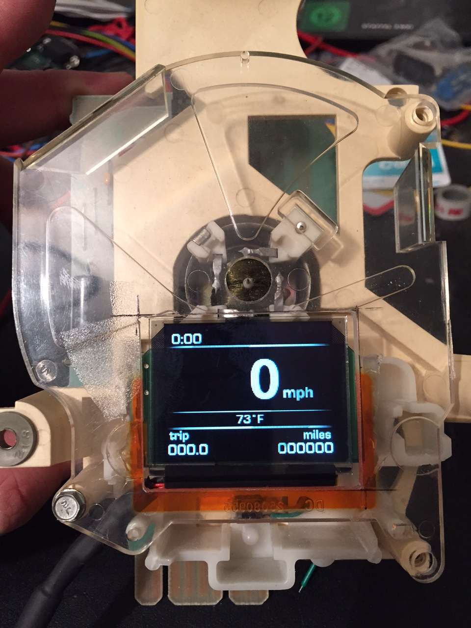
Finally, the unit was powered up in bootloader mode, which displays a frame on the display marking the maximum usable area, which is ideal for verification of the cut in the face plate. A fresh coat of spray glue may need to be applied to the gauge face and before it is reglued to the plexiglass. Don't forget to remove the protective film at this time which may be on the OLED or TFT display.
To reinstall the needle, the speedo must be powered up and the needle pushed on pointing to zero. A better way to do it is to hook up a signal generator with a 60 Hz sine wave to the VSS input of the speedo and push the needle on pointing to 54 mph.
Now it's time to put the speedometer back into the cluster housing. There is still one more hole to drill. At the lower RH corner of the circuit board there is a Mini-USB jack. You want this jack to be accessible from under the dash, so drill a hole here that allows you to insert a Mini-USB cable here. Once this is done, reassemble the cluster and put it back into the car. It's a smart idea to keep the USB cable installed and route it to a convenient location (like e.g. the ash tray area), which makes software updates a breeze!
Fiero installation
The Fiero-specific version of the DashComputer is a lot simpler because everything is integrated on the main speedometer circuit board, and some connections are already present on the stock connector while others are internal or optional/not needed. The minimal installation of the Fiero only requires 3 extra wires (battery to keep clock running, outside temp sensor, ALDL input and optionally bootloader select for flash updates), and optinally another 2-4 wires for some extra things like IP illumination.
This is the new layout of the Fiero speedometer connector C1 (the terminals required are available at NAPA for instance for $1 each):
Connector pinouts
| A | IP Illumination (optional) | grey |
| B | Battery 12V, hot at all times | orange |
| C | Outside temperature sensor input | green/white |
| D | reserved | |
| E | reserved | |
| F | ALDL (160/8192 baud) | orange |
| G | GPS RS232 input (optional) | TBD |
| H | GMLAN / CANH (circuit board option) | TBD |
| J | CANL (circuit board option) | TBD |
| K | reserved | |
| L | Pushbutton extension input (optional) | TBD |
| M | 4000 ppm speed signal to Digital Cruise Module or Electro Hydraulic Power Steering Module | brown |
| N | reserved | |
| P | Ground | black/white |
| R | Vehicle Speed Sensor Ground | purple/white |
| S | Vehicle Speed Sensor Signal | yellow |
| T | 12V Ignition | yellow/black |
| U | 2000 ppm Speed Signal to ECM and Vacuum operated cruise control module | dark green/white |