
General installation remarks
The universal DashComputer is versatile and can be used with different vehicles, and not all features are supported by all vehicles and/or all firmwares. Because of this, these installation instructions can only be a guideline, and you have to determine which features are available in your installation or are maybe supported in a future version. The following is a description of the installation into fourth generation Firebirds/Camaros, collectively called F-bodies. The installation of a Fiero specific version is covered separately!
Installation of the display unit
DashScan consists of two modules: the main module (or just module) and the display unit. They are connected with a 1ft (30 cm) black 8 wire cable. The display unit is the only thing you'll see of the DashComputer once it's installed, so you need to be extra careful to end up with a professional, stock-looking setup. The display module is designed to replace the digital odometer LCD display found in the 96+ Firebirds and Camaros.
To install the display module the IP cluster needs to be removed from the vehicle and modified, unless you want to mount the display elsewhere. A hole must inevitably be cut into the gauge face, be sure you work super clean here! Start by marking and removing the needles and then separating gauge face and plexiglass support. You need to cut or enlarge a hole for the display in the plexiglass support. The hole in the plexiglass support of the gauge face needs to be a rectangular opening at least 43mm wide and 34mm high to accomodate the display glass. The opening may be slightly larger, but not too much!
Reinstall the gauge face and mark the OLED display opening with a removable marker from behind (Caution: don't cut this area out! The marking is just for reference!).
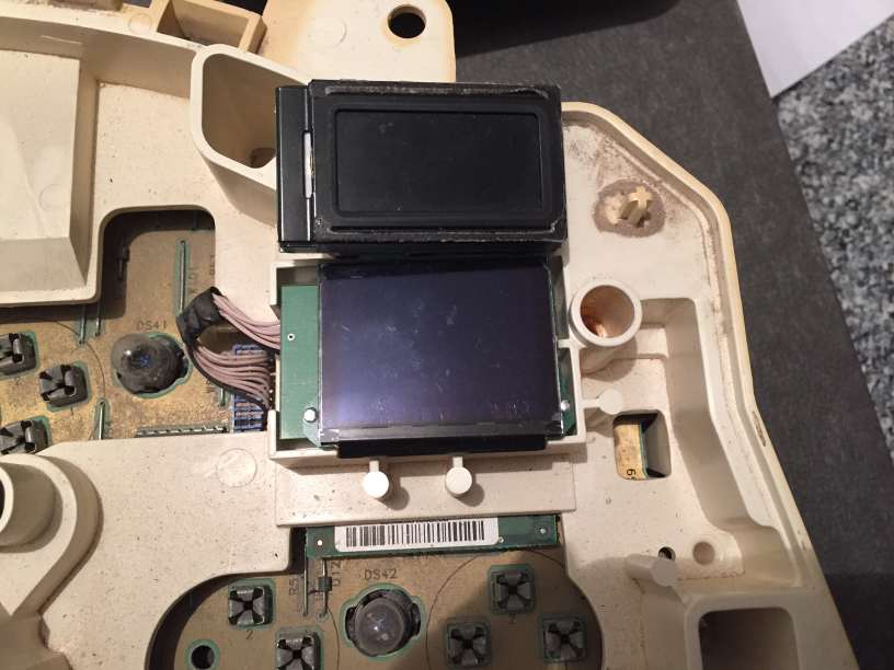
The image above shows the F-body display in the instrument cluster cradle compared to the stock LCD odometer module. Note that the width of the displays is about the same, the plexiglass has to be trimmed about 1mm at the top, and of course more at the bottom to accommodate the taller OLED display.
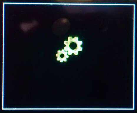
Next is the critical part: cutting a hole in the gauge face. If you screw up here, it will be visible later on! The goal is to cut a clean (!) hole that is just large enough to show the entire visible area of the OLED, but not more! Fortunately the OLED can help us here. Hook up the OLED display, and power up the module. If you enter the Bootloader, the OLED will display a white frame to mark the maximum display area. The black margin outside that frame will always be black, so this is your margin for error when cutting. Now find the marking you made on the backside of the face plate, this is the outline of the OLED. Obviously you want an opening smaller than this! Now cut a small opening into the gauge face to reveal the OLED display. DO NOT cut to the edge of the marking, or you'll reveal the edges of the OLED, which you don't want to do! Now slowly enlarge the opening until the white frame on the OLED is visible all around.
Now you can clean up the edge of the face plate with a ruler and an exacto knife. Be sure not to damage the visible area and try to end up with a clean cut edge. Now the needles can be reinstalled again. Hook up the display to the flexible red wire bundle and route the connection cable to the location of the module. For the Fiero this is simple, as there is no module and the red display cable plugs directly into the new speedo board.
Using the existing Trip/Oil reset button on the F-body
The late model F-body instrument cluster (99-02, with serial data/Class 2 capability) has an existing trip reset button that can be used to operate DashComputer without sacrificing the oil reset function! The modification to the cluster is very simple and only requires two readily available components and a bit of wire. You will need:
- 1 Transistor BC547 or similar
- 1 47k Resistor (Coded Yellow, Purple, Orange, Gold)
The installation of these components is simple and straightforward. Please use these pictures for reference.
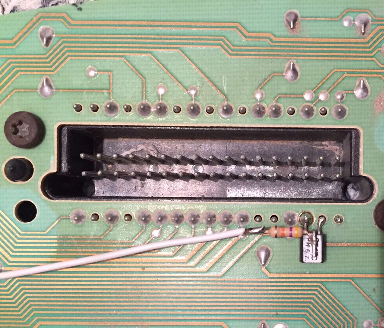
Look at the transistor's face side (the one with the markings) and the three wires pointing up. Then bend the center pin up and back 270 degrees until is lies flat on the markings. bend the remaining two pins down. Then cut the wires so they're as short as in the pictures. Next solder the two outer pins to the black connector as shown in the picture. You will solder the emitter to the ground pin B15, and the collector to the unused pin B16 to the right of it. This will also fix the transistor mechanically. Test mount the black back cover to verify the transistor fits into the existing cutout.
Next take the resistor and bend one wire 90 degrees and cut it to 2 mm length. Solder this "leg" to the center pin of the transistor that you bent up as shown in the pictures. Cut the other end of the resistor to 2 mm and solder a thin wire to it. Make sure the resistor can't touch anything conductive, e.g. by using shrink tubing (not shown in the pictures for clarity). Now locate the trip/oil reset microswitch, it has two solder joints. Route the thin wire to the inner solder joint and fix the wire with hot glue or electrical tape. When the black cover is back on, this modification will be almost invisible. And since it uses an unused pin in the connector, it doesn't interfere with anything else!
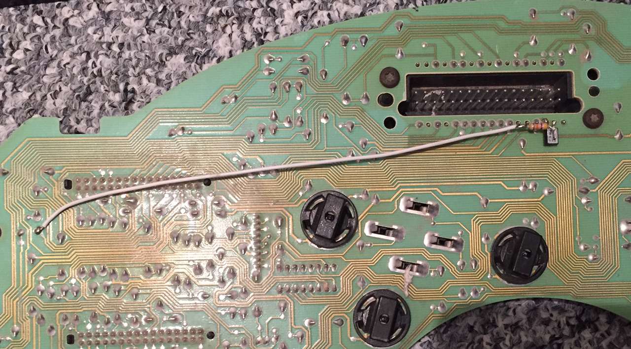
Now the modification needs to be connected to DashComputer. Just remove the TPA bar from the black IP cluster connector and insert a terminal with wire into the B16 cavity. This wire then goes to C9 of the DashComputer connector ("trip reset" input). I am aware that the instrument cluster connector is hard to work with because of space constraints, so loook at the connector on the IP cluster that you just modified. The new connection is the lower row, second pin from the driver side of the cluster. This is B16! Insert the new terminal into the corresponding cavity on the connector, and you're good to go!
Electrical connections
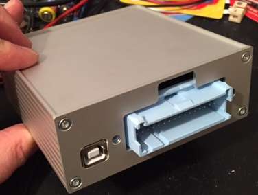
The DashComputer is connected to the vehicle via a 32-pin Micropack Connector (Delphi part number 1211 0207). The connector supports the most common connections with multicolored wires. You need to purchase the proper terminals, crimp them to wires in a color of your choice and connect them to your car if you need additional connections. Regarding the wire gauge, you need to get the terminals suitable for the wire gauge you're using, and it's a good start to use the same gauge wire of the circuit you're splicing to. If in doubt, use AWG 18-20, since DashComputer doesn't use any high-current signals.
Apart from a crimping tool, it's advisable to purchase the proper red terminal pick (P/N 1203 1876) to be able to remove a terminal effortlessly. When everything is wired correctly, install the grey resp. blue Terminal Position Assurance (TPA) into the blue connector. Part numbers are 1204 5889 and 1204 5890.
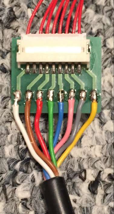 The display module is connected through the 32-pin Micropack connector. It may be a good idea to route the wires to the display module through an 8-pin unsealed Metripack connector. This allows the removal of the IP cluster containing the display module by simply disconnecting that 8-pin connector. The location of the connector of course depends on the installation situation. I used an 8-wire flex phone cable and an adapter to the delicate connector used on the display module.
The module should be wired as close to the display module as possible, and all wires should be run along existing wiring harnesses if at all possible. Please consult your vehicle's technical manual for wiring details.
The display module is very compact and can be installed in a variety of locations. Starting the bootloader can help the installation because the bootloader screen is framed by a 1 pixel border that can be used to precisely position the display module in an existing dash opening or possible cut or enlarge an opening in the instrument cluster gauge faceplate.
The wiring color suggestions follow GM's coloring scheme, but of course any wire colors that are available during installation can be used. If colors are given, they are suggestions only.
Connector pinouts
TerminalDesciptionColor
|
TerminalDesciptionColor
|
TerminalDesciptionColor
|
TerminalDesciptionColor
|
The essentials
There are only a few minimum connections that you really need to make apart from the display module. Of course the DashComputer needs power. C16/D16 should be connected to a a good ground and a fused ignition voltage (Hot in Run and Start). To facilitate dimming of the display, the IP-illumination input must be connected to the IP dimmer circuit. On GM vehicles this wire is usually grey and carries 6-12V depending on the dimmer thumbwheel setting.
Since you probably want to flash new firmware at some point in the future, it's a good idea to wire C14 along a USB cable to a pushbutton switch to ground in a hidden, yet accessible location.
In order to operate the DashComputer at least one pushbutton switch ("trip reset") is required. It is wired to C9/D9, which is the IP cluster modification explained above. Additional pushbutton switches are supported depending on firmware version - "Set/Menu"" and "Enter" switches are connected to C8/D8 respectively.
And in order to display current speed and trip computer functions, the VSS input (C5) must be connected to a suitable signal on the vehicle. DashComputer can only operate with the VSS buffered output signal of 2000 or 4000 pulses per mile (depending on firmware). It does not work directly with the VSS sensor, which can generate voltages of dozens of volts! Refer to your vehicle's technical manual for circuit information! I was told by user Viper on LS1TECH that on the Firebird LT1 you can get the speed signal from connector C220 cavity G. Connector C220 is white and along the passenger kick panel. On the Camaro there is speed sensitive sound so I they may be able to tap into the speed signal at the radio harness.
To display the outside temperature, a GM 97-2013 outside temperature sensor P/N 1024 8414 can be connected between C6 and D6. It is important to use D6 as sensor ground to get a clean reading.
Compass
DashComputer can be connected to an optional compass sensor, which is recognized automatically. DashComputer provides power to the compass module and has four directional inputs for North, South, East and West.
Optional stuff
The rest of the terminals are for optional circuits that may not be supported by all firmwares. DashComputer has a PWM output that allows for connecting a 12V LED circuit and dims it using pulse width modulation proportional to the IP illumination input. This can be useful for designing custom instrument cluster lighting. Please note that the current may not exceed 0.7 Amps!
Certain firmwares support 160/8192 baud ECM communication through the ALDL connector to display e.g. fuel mileage or gear information. The ALDL data circuit can be connected to D7. J1850 PWM protocol is unfortunately not supported.
Certain firmwares support connection of a standard NMEA GPS receiver with a RS232 compatible output. The RS232 output can be connected to D14.
Certain firmwares support connecting suitable devices using a CAN bus or GMLAN. The CAN bus signals (CANL/CANH) are provided on C13/D13. This should also be compatible with GMLAN if CANH is connected to the GMLAN bus and CANL is connected to ground, but a 120 Ohms termination resistor must be removed from the circuit board if the device is to be connected to GMLAN!
Future firmware may support additional pushbutton inputs. These are connected to the default button input C9 in series with a resistor (4.7k, 10k, 22k, 47k, 100k, etc.) as specified by the firmware documentation.
Future firmwares may support an inside temperature sensor, which would be connected to C7 and D6.
The battery input (C15) is usually not needed, because the unit contains a button cell backup battery. If the button cell battery is removed and a solder jumper is moved, the unit can also use the car battery to supply backup power to the clock.