
Color TFT/OLED Trip Computer
Ich habe 2015 mit der Entwicklung eines Fahrtcomputers für Firebirds/Camaros begonnen, und irgendwann kam mir die Einsicht, dass so ein Teil auch im Fiero nicht schlecht sein würde. Daher stelle ich die Informationen über dieses Projekt auch hier zur Verfügung, allerdings handelt es sich dabei um ein Projekt, das sich noch in Entwicklung befindet, und ausserdem ist der Text vorerst noch Englisch. Wenn die Entwicklung abgeschlossen ist, werde ich das Ganze vielleicht auch eindeutschen, aber interessiert den Einen oder Anderen ja auch die Vorabinfo und Entstehungsgeschichte...
The DashComputer project
 This project started out as an idea for replacement of the Camaro's LCD odometer with a color OLED display with graphics capabilities. Based on a monochrome OLED display concept I had designed for the 98-02 F-body instrument cluster and different embedded trip computers I have designed and built for the Fiero instrument cluster work began on a versatile computer control module for dash instrument clusters of various vehicles. The project was named "DashComputer".
 While initially targeted for the Camaro only it quickly became apparent that this gadget would be useful for more vehicles, since the display with its compact dimensions of 1.6" diagonally would fit into a variety of vehicles. The display is about 1/2" thick and the advantages of OLED are high-contrast, crystal clear colors combined with a wide temperature range and wide viewing angle. The only downside is the limited lifetime due to burn-in over its lifetime of 12.000 hrs (although a slight burn-in can be noticeable considerably sooner, especially if the display is run at high contrast settings). But, if the burn-in really gets distracting: the display isn't too expensive and can easily be replaced. Yet, the OLED does decay so alternatively a TFT of virtually identical dimensions can be used as well, although the contrast isn't as crisp as the OLED's.
 Due to the limited space in an instrument cluster the display unit is a sandwich of two circuit boards, yielding compact dimensions and mechanical stability for the fragile display glass with silicon chip-on-flex circuit board. The display unit is connected to the control module via 8 wires. The control module is about 4x3" and should be located close to the instrument cluster to keep the wires to the display module short. Since the Fiero instrument cluster is modular, it was feasible to design a replacement circuit board for the speedometer module that integrates all trip computer and speedometer components on a single board, thus eliminating the separate electronic control module and connector that the F-body and other cars need.
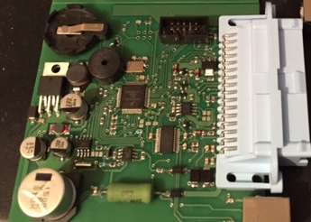
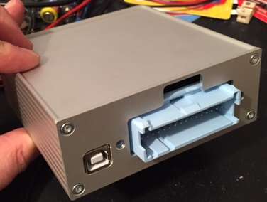
 This electronic control module is the heart of the system, serving as a platform for a variety of applications. The module is customized to its vehicle through a custom firmware that is user updateable via USB. The universal module is connected to the vehicle using a standard Delphi 32-pin Micropack connector also used by GM in vehicle electronics, assuring availability of connector components for years to come. The Fiero module is connected through the stock speedometer connector. Since updates can be performed on-board through USB, the universal module can be mounted hidden anywhere under the dash without the need to physically access the module for software updates.
Key features
The hardware supports the following features:
- Connects to a serial TFT or OLED module
- Customizeable to vehicle
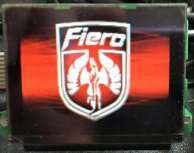
- Customizeable with color startup ("splash") screen with 256 out of 262K colors
- Customizeable with color background screen with 256 out of 262K colors
- Many customizeable items
- Firmware USB updateable by user, no special hardware required
- Firmware can be updated using Android phone/tablet
- Odometer settable by user application
- 2000 ppm / 4000 ppm vehicle speed inputs found in many GM cars
- Up to two temperature sensor inputs using standard GM temperature sensors
- Can be configured to display system voltage
- Multiple pushbutton inputs
- Battery backed clock / trip computer values using either button cell or vehicle battery (Fiero: vehicle battery only)
- Input for digital Dinsmore compass sensor module (not available on Fiero unit)
- ALDL ECM communication suitable for C3 and P4 computer systems (160 / 8192 baud)
- IP illumination voltage input and PWM illumination LED driver output for custom LED IP illumination
- Piezo speaker for user alerts (8 Ohm speaker for Fiero version)
- RS232 compatible input for NMEA GPS mouse
- CAN bus for interfacing with select radio head units and future extensions.
Technial data:
- Supports SPI OLED and TFT modules (SSD1353 OLED or ST7735 TFT controller), 262.000 colors (18 bit)
- 25 MHz Freescale automotive grade microcontroller with 240K memory
- FTDI USB controller supported by Windows/MacOS/Linux for firmware updates
- Current requirement with ignition off < 1mA
- LED driver delivering up to 700 mA for custom cluster illumination, e.g. 140 LEDs of 20mA in strings of four (not available on Fiero model)
- Standard CAN bus driver with 120 Ohms termination on board
- Optional backup battery: CR2032 button cell, ~10 years endurance (not on Fiero)
- OLED operating lifetime: 16000hrs @60Cd/m2
Not all functions are available in all firmwares, but the hardware platform is compatible across all vehicles!
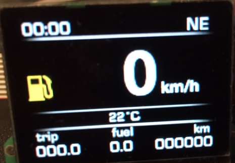
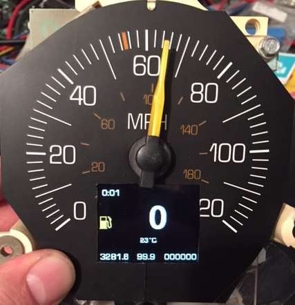
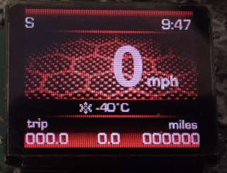
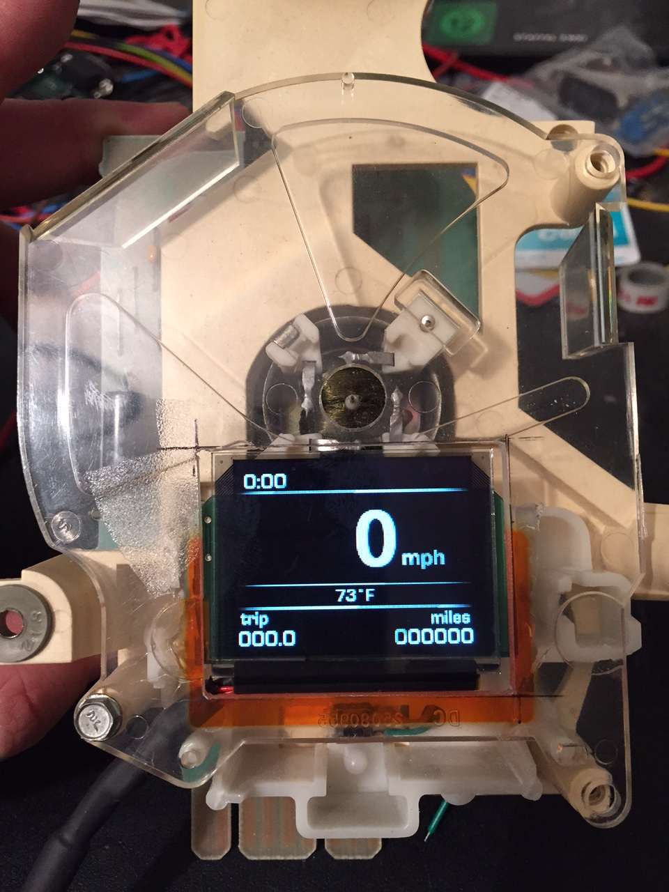
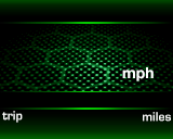
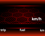
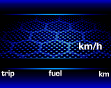
Display layout: top bar
The trip computer is really simple to operate. No user interaction is required for operation, the screen just displays useful information. The screen is divided into four separate areas. The top bar displays current time and (if a compass sensor is installed) current heading. Please note that the Fiero specific circuit board does not support a compass sensor! Time display can be configured to display either 12 or 24 hour format. To set the clock, push the "set" pushbutton until the hour display starts blinking. Now push the "trip reset" pushbutton several times to set the correct hour. If the correct hour is displayed, push the "trip reset" pushbutton for 3 seconds. Now the minutes display will be flashing. Similarly, push the "trip reset" pushbutton several times until the correct minutes are displayed. If the time is correct, push the "trip reset" pushbutton again for 3 seconds to return to normal operating mode. Note: if a GPS is connected to the trip computer, its information will be used to adjust the clock, but only to adjust for deviations of a few minutes.
The top center position is used to display current fuel consumption (Fiero 86-88 V6 ECM only!). This is only displayed if mileage information is received from a suitable ECM, otherwise it is blank.
The positions of the top items as well as the alignment of the text can be configured, so the display shown on this page is only the default configuration.
The bottom bar
The bottom bar displays trip computer information in the left corner and the car's mileage in the right corner. The trip display can display various items, these can be changed by pushing the "trip reset" pushbutton, which cycles through these items:
- Trip distance (always three digits, decimal point and a single digit, e.g. 0123.3) The distance is in the configured unit, i.e. either km or miles.
- Trip time (always time format with a color, e.g. 1:23)
- Trip average speed (always 1-3 digits without colon or decimal point, e.g. 123). The speed is displayed in the same unit as the vehicle speed in the main window
- Trip average fuel consumption (always two digits, decimal point and a single digit, e.g. 12.3)
By pressing the "trip reset" pushbutton for more than a second (this duration is configurable), all trip data resets to zero. If the trip data overflows, it also resets to zero.
On the Fiero with a 86-88 ECM, total fuel consumed information is displayed in the center of the bottom bar. The fuel counter counts up, and should be reset when the car is refueled. To reset the fuel counter, turn on the ignition after refueling while keeping the "trip reset" pushbutton pressed. A short beep is played to confirm successful reset.
The info bar
Above the bottom bar is the info bar, which currently only contains temperature information from the outside temperature sensor input. The display can be configured to display either Celsius or Fahrenheit. If the temperature is near freezing, a snowflake is also displayed here and a warning beep is sounded to alert the driver of hazardous road conditions. The warning temperature threshold is also configurable. Alternatively you can display the system battery voltage here.
Main window
The remaining screen area is called the main window. The center of the main window prominently displays the current vehicle speed in either mph or km/h. Again, several parameters influencing the speed display can be configured. The area to the left of the current speed can display a yellow "low fuel icon" on the Fiero. For this feature the fuel counter is used and internally subtracts the used fuel from a configurable fuel tank capacity. If the consumption exceeds the configured threshold, an audible beep is sounded and the warning icon is displayed. The icon disappears if the fuel counter is reset after refueling.
The area to the right above the km/h or mls unit display is reserved for GPS use. If a suitable GPS receiver is connected to the GPS input, a satellite dish is displayed in either red or green to signal GPS lock status, and displays the number of satellites next to it. If lock has been established for a configurable number of seconds, the satellite symbol disappears. If the GPS information contains a heading, this heading can be used to supply the heading information for the top bar if no compass sensor is present. The GPS information can be used to alert the user of local points of interest (POI) if the car is close enough. A beep is sounded and a configurable icon is displayed while the POI is near.
General installation remarks
The universal DashComputer is versatile and can be used with different vehicles, and not all features are supported by all vehicles and/or all firmwares. Because of this, these installation instructions can only be a guideline, and you have to determine which features are available in your installation or are maybe supported in a future version. The following is a description of the installation into fourth generation Firebirds/Camaros, collectively called F-bodies. The installation of a Fiero specific version is covered separately!
Installation of the display unit
DashScan consists of two modules: the main module (or just module) and the display unit. They are connected with a 1ft (30 cm) black 8 wire cable. The display unit is the only thing you'll see of the DashComputer once it's installed, so you need to be extra careful to end up with a professional, stock-looking setup. The display module is designed to replace the digital odometer LCD display found in the 96+ Firebirds and Camaros.
To install the display module the IP cluster needs to be removed from the vehicle and modified, unless you want to mount the display elsewhere. A hole must inevitably be cut into the gauge face, be sure you work super clean here! Start by marking and removing the needles and then separating gauge face and plexiglass support. You need to cut or enlarge a hole for the display in the plexiglass support. The hole in the plexiglass support of the gauge face needs to be a rectangular opening at least 43mm wide and 34mm high to accomodate the display glass. The opening may be slightly larger, but not too much!
Reinstall the gauge face and mark the OLED display opening with a removable marker from behind (Caution: don't cut this area out! The marking is just for reference!).
The image above shows the F-body display in the instrument cluster cradle compared to the stock LCD odometer module. Note that the width of the displays is about the same, the plexiglass has to be trimmed about 1mm at the top, and of course more at the bottom to accommodate the taller OLED display.
Next is the critical part: cutting a hole in the gauge face. If you screw up here, it will be visible later on! The goal is to cut a clean (!) hole that is just large enough to show the entire visible area of the OLED, but not more! Fortunately the OLED can help us here. Hook up the OLED display, and power up the module. If you enter the Bootloader, the OLED will display a white frame to mark the maximum display area. The black margin outside that frame will always be black, so this is your margin for error when cutting. Now find the marking you made on the backside of the face plate, this is the outline of the OLED. Obviously you want an opening smaller than this! Now cut a small opening into the gauge face to reveal the OLED display. DO NOT cut to the edge of the marking, or you'll reveal the edges of the OLED, which you don't want to do! Now slowly enlarge the opening until the white frame on the OLED is visible all around.
Now you can clean up the edge of the face plate with a ruler and an exacto knife. Be sure not to damage the visible area and try to end up with a clean cut edge. Now the needles can be reinstalled again. Hook up the display to the flexible red wire bundle and route the connection cable to the location of the module. For the Fiero this is simple, as there is no module and the red display cable plugs directly into the new speedo board.
Using the existing Trip/Oil reset button on the F-body
The late model F-body instrument cluster (99-02, with serial data/Class 2 capability) has an existing trip reset button that can be used to operate DashComputer without sacrificing the oil reset function! The modification to the cluster is very simple and only requires two readily available components and a bit of wire. You will need:
- 1 Transistor BC547 or similar
- 1 47k Resistor (Coded Yellow, Purple, Orange, Gold)
The installation of these components is simple and straightforward. Please use these pictures for reference.
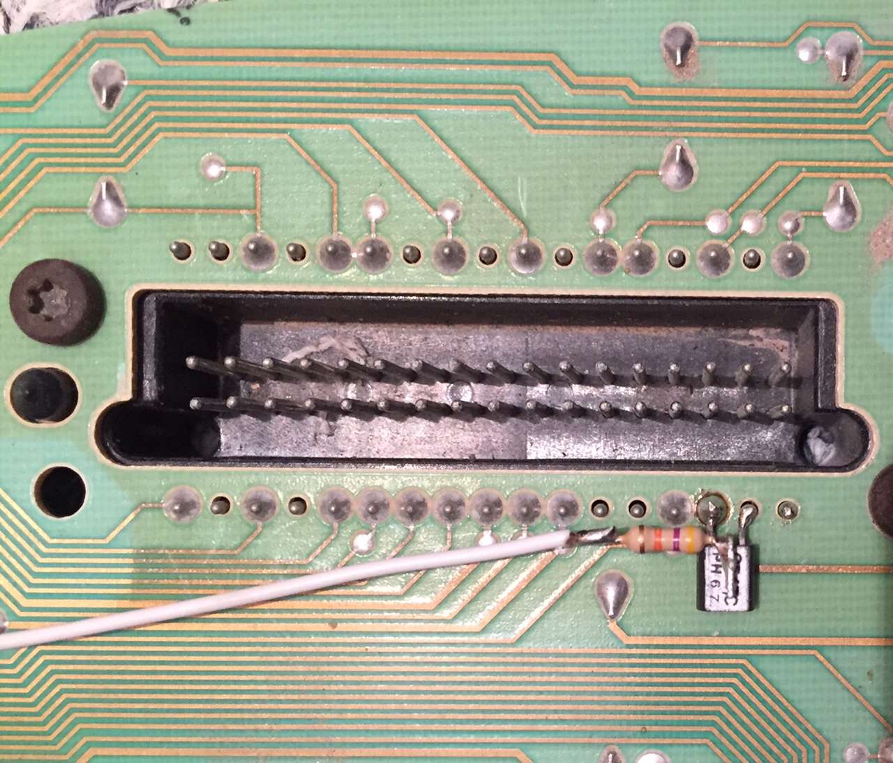
Look at the transistor's face side (the one with the markings) and the three wires pointing up. Then bend the center pin up and back 270 degrees until is lies flat on the markings. bend the remaining two pins down. Then cut the wires so they're as short as in the pictures. Next solder the two outer pins to the black connector as shown in the picture. You will solder the emitter to the ground pin B15, and the collector to the unused pin B16 to the right of it. This will also fix the transistor mechanically. Test mount the black back cover to verify the transistor fits into the existing cutout.
Next take the resistor and bend one wire 90 degrees and cut it to 2 mm length. Solder this "leg" to the center pin of the transistor that you bent up as shown in the pictures. Cut the other end of the resistor to 2 mm and solder a thin wire to it. Make sure the resistor can't touch anything conductive, e.g. by using shrink tubing (not shown in the pictures for clarity). Now locate the trip/oil reset microswitch, it has two solder joints. Route the thin wire to the inner solder joint and fix the wire with hot glue or electrical tape. When the black cover is back on, this modification will be almost invisible. And since it uses an unused pin in the connector, it doesn't interfere with anything else!
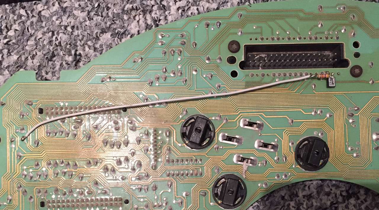
Now the modification needs to be connected to DashComputer. Just remove the TPA bar from the black IP cluster connector and insert a terminal with wire into the B16 cavity. This wire then goes to C9 of the DashComputer connector ("trip reset" input). I am aware that the instrument cluster connector is hard to work with because of space constraints, so loook at the connector on the IP cluster that you just modified. The new connection is the lower row, second pin from the driver side of the cluster. This is B16! Insert the new terminal into the corresponding cavity on the connector, and you're good to go!
Electrical connections
The DashComputer is connected to the vehicle via a 32-pin Micropack Connector (Delphi part number 1211 0207). The connector supports the most common connections with multicolored wires. You need to purchase the proper terminals, crimp them to wires in a color of your choice and connect them to your car if you need additional connections. Regarding the wire gauge, you need to get the terminals suitable for the wire gauge you're using, and it's a good start to use the same gauge wire of the circuit you're splicing to. If in doubt, use AWG 18-20, since DashComputer doesn't use any high-current signals.
Apart from a crimping tool, it's advisable to purchase the proper red terminal pick (P/N 1203 1876) to be able to remove a terminal effortlessly. When everything is wired correctly, install the grey resp. blue Terminal Position Assurance (TPA) into the blue connector. Part numbers are 1204 5889 and 1204 5890.
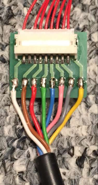 The display module is connected through the 32-pin Micropack connector. It may be a good idea to route the wires to the display module through an 8-pin unsealed Metripack connector. This allows the removal of the IP cluster containing the display module by simply disconnecting that 8-pin connector. The location of the connector of course depends on the installation situation. I used an 8-wire flex phone cable and an adapter to the delicate connector used on the display module.
The module should be wired as close to the display module as possible, and all wires should be run along existing wiring harnesses if at all possible. Please consult your vehicle's technical manual for wiring details.
The display module is very compact and can be installed in a variety of locations. Starting the bootloader can help the installation because the bootloader screen is framed by a 1 pixel border that can be used to precisely position the display module in an existing dash opening or possible cut or enlarge an opening in the instrument cluster gauge faceplate.
The wiring color suggestions follow GM's coloring scheme, but of course any wire colors that are available during installation can be used. If colors are given, they are suggestions only.
Connector pinouts
TerminalDesciptionColor
|
TerminalDesciptionColor
|
TerminalDesciptionColor
|
TerminalDesciptionColor
|
The essentials
There are only a few minimum connections that you really need to make apart from the display module. Of course the DashComputer needs power. C16/D16 should be connected to a a good ground and a fused ignition voltage (Hot in Run and Start). To facilitate dimming of the display, the IP-illumination input must be connected to the IP dimmer circuit. On GM vehicles this wire is usually grey and carries 6-12V depending on the dimmer thumbwheel setting.
Since you probably want to flash new firmware at some point in the future, it's a good idea to wire C14 along a USB cable to a pushbutton switch to ground in a hidden, yet accessible location.
In order to operate the DashComputer at least one pushbutton switch ("trip reset") is required. It is wired to C9/D9, which is the IP cluster modification explained above. Additional pushbutton switches are supported depending on firmware version - "Set/Menu"" and "Enter" switches are connected to C8/D8 respectively.
And in order to display current speed and trip computer functions, the VSS input (C5) must be connected to a suitable signal on the vehicle. DashComputer can only operate with the VSS buffered output signal of 2000 or 4000 pulses per mile (depending on firmware). It does not work directly with the VSS sensor, which can generate voltages of dozens of volts! Refer to your vehicle's technical manual for circuit information! I was told by user Viper on LS1TECH that on the Firebird LT1 you can get the speed signal from connector C220 cavity G. Connector C220 is white and along the passenger kick panel. On the Camaro there is speed sensitive sound so I they may be able to tap into the speed signal at the radio harness.
To display the outside temperature, a GM 97-2013 outside temperature sensor P/N 1024 8414 can be connected between C6 and D6. It is important to use D6 as sensor ground to get a clean reading.
Compass
DashComputer can be connected to an optional compass sensor, which is recognized automatically. DashComputer provides power to the compass module and has four directional inputs for North, South, East and West.
Optional stuff
The rest of the terminals are for optional circuits that may not be supported by all firmwares. DashComputer has a PWM output that allows for connecting a 12V LED circuit and dims it using pulse width modulation proportional to the IP illumination input. This can be useful for designing custom instrument cluster lighting. Please note that the current may not exceed 0.7 Amps!
Certain firmwares support 160/8192 baud ECM communication through the ALDL connector to display e.g. fuel mileage or gear information. The ALDL data circuit can be connected to D7. J1850 PWM protocol is unfortunately not supported.
Certain firmwares support connection of a standard NMEA GPS receiver with a RS232 compatible output. The RS232 output can be connected to D14.
Certain firmwares support connecting suitable devices using a CAN bus or GMLAN. The CAN bus signals (CANL/CANH) are provided on C13/D13. This should also be compatible with GMLAN if CANH is connected to the GMLAN bus and CANL is connected to ground, but a 120 Ohms termination resistor must be removed from the circuit board if the device is to be connected to GMLAN!
Future firmware may support additional pushbutton inputs. These are connected to the default button input C9 in series with a resistor (4.7k, 10k, 22k, 47k, 100k, etc.) as specified by the firmware documentation.
Future firmwares may support an inside temperature sensor, which would be connected to C7 and D6.
The battery input (C15) is usually not needed, because the unit contains a button cell backup battery. If the button cell battery is removed and a solder jumper is moved, the unit can also use the car battery to supply backup power to the clock.
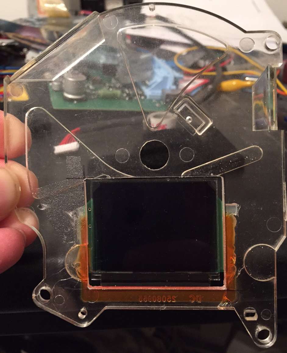
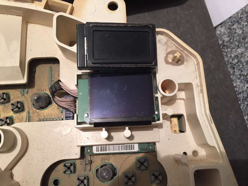
Installation of the display module into the Fiero speedo is not as simple as for the F-body cluster. It requires not only to remove the speedometer from the cluster, but also to completely disassemble it!
The indicator needle has to be pulled off carefully and the plexiglass carrier has to be separated from the faceplate and the support frame. Now a rectangular opening must be milled into the plexiglass, sacrificing one of the two air core motor positioning posts. Don't worry, it's not needed. The opening must be milled just large enough to accomodate the TFT or OLED module (about 43 x 34 mm). The module can't be moved up higher because then this would interfere with the air core motor, if it's moved lower, it is no longer completely visible when installed in the cluster.
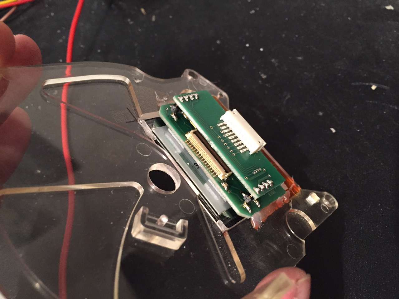
The display module can now be installed and aligned into the opening in the plexiglass and fixed with hot glue. This has the advantage of being able to correct the position later on, which is not the case if epoxy is used for installation. The carrier circuit board is slightly wider than the display to allow glueing it to the plexiglass.
Care must be taken not to get glue on the display glass, and the flexible circuit board is also very delicate and should not be bent or otherwise folded, so it's better to have a larger opening towards the bottom of the plexiglass to have some space for the flex board. This part of the speedometer will not be visible after installation anyway. Carefully push the small red display harness into the white connector on the TFT/OLED module and set aside the Plexiglass with display and wiring.
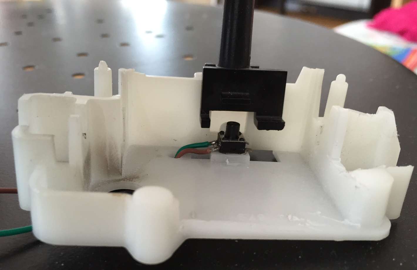
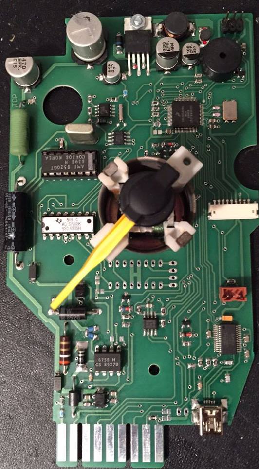
To operate DashComputer at least one switch is required, and it's a smart idea to use the now obsolete trip odometer stalk for this purpose. The trip odometer and drive gears need to be completely removed, and some parts cut off if they are interfering with the display board. Test fit things carefully and then cut away e.g. with a Dremel, use the image above for reference. Then a small microswitch must be glued (this time with epoxy!) as shown in the picture so that the actuator (the little flap) on the pushbutton operates the microswitch when it is pushed. A three wire pigtail is provided to connect up to two switches to the board. The center wire is common, the outer two are connected to the "trip reset" and "set clock/menu" switches. The "trip reset" switch is the one operated when you push the odometer stalk.
Now the new circuit board (below) is ready for assembly. Assemble the support frame with the board and air core motor, place plexiglass on top and plug the two connectors into the new circuit board (the small white display and even smaller switch connectors are at the right side of the board). Reinstall all screws and tighten them very carefully: the material is 30 years old and probably brittle.
Finally, the unit was powered up in bootloader mode, which displays a frame on the display marking the maximum usable area, which is ideal for verification of the cut in the face plate. A fresh coat of spray glue may need to be applied to the gauge face and before it is reglued to the plexiglass. Don't forget to remove the protective film at this time which may be on the OLED or TFT display.
To reinstall the needle, the speedo must be powered up and the needle pushed on pointing to zero. A better way to do it is to hook up a signal generator with a 60 Hz sine wave to the VSS input of the speedo and push the needle on pointing to 54 mph.
Now it's time to put the speedometer back into the cluster housing. There is still one more hole to drill. At the lower RH corner of the circuit board there is a Mini-USB jack. You want this jack to be accessible from under the dash, so drill a hole here that allows you to insert a Mini-USB cable here. Once this is done, reassemble the cluster and put it back into the car. It's a smart idea to keep the USB cable installed and route it to a convenient location (like e.g. the ash tray area), which makes software updates a breeze!
Fiero installation
The Fiero-specific version of the DashComputer is a lot simpler because everything is integrated on the main speedometer circuit board, and some connections are already present on the stock connector while others are internal or optional/not needed. The minimal installation of the Fiero only requires 3 extra wires (battery to keep clock running, outside temp sensor, ALDL input and optionally bootloader select for flash updates), and optinally another 2-4 wires for some extra things like IP illumination.
This is the new layout of the Fiero speedometer connector C1 (the terminals required are available at NAPA for instance for $1 each):
Connector pinouts
| A | IP Illumination (optional) | grey |
| B | Battery 12V, hot at all times | orange |
| C | Outside temperature sensor input | green/white |
| D | reserved | |
| E | reserved | |
| F | ALDL (160/8192 baud) | orange |
| G | GPS RS232 input (optional) | TBD |
| H | GMLAN / CANH (circuit board option) | TBD |
| J | CANL (circuit board option) | TBD |
| K | reserved | |
| L | Pushbutton extension input (optional) | TBD |
| M | 4000 ppm speed signal to Digital Cruise Module or Electro Hydraulic Power Steering Module | brown |
| N | reserved | |
| P | Ground | black/white |
| R | Vehicle Speed Sensor Ground | purple/white |
| S | Vehicle Speed Sensor Signal | yellow |
| T | 12V Ignition | yellow/black |
| U | 2000 ppm Speed Signal to ECM and Vacuum operated cruise control module | dark green/white |
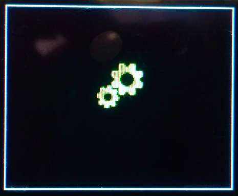
The bootloader is a small program in the control module that allows firmware updates to be programmed into the module via USB. The bootloader is in protected memory, so even if something goes wrong you should still be able to access the bootloader and try again.
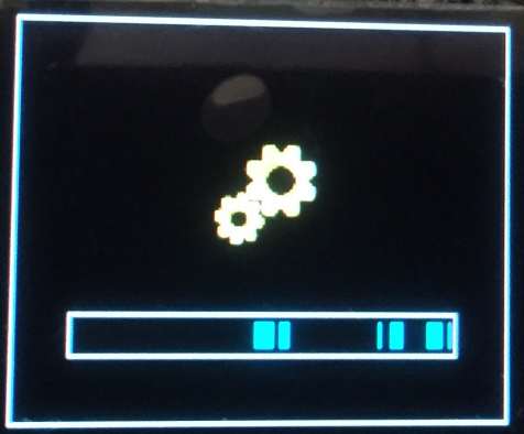
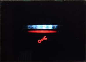
You won't see the bootloader unless either no firmware is present, or you forced the unit into bootloader mode. Memory is usually only empty if you got a blank DashComputer, or if you erased the firmware yourself. So you'll usually have to force the unit into bootloader mode. In order to force the unit into bootloader mode, ground the bootloader input with the ignition off and then turn on the ignition. An alternative and simpler method is to hook up a terminal to the USB port and enter the magic numbers 25051977 and hit return. This will send you to the bootloader as well, but this method may not work if the firmware is somehow corrupt. The OLED screen should show the bootloader gear icon:
Now connect DashComputer to a computer or laptop using a USB-cable. The first time this is done the computer may look for a suitable driver. If no driver is found, you can download a suitable driver from FTDI. This installs a virtual COM port (VCP) on your computer.
Now open a simple terminal program like e.g. Hyperterm. Select the newly installed virtual COM port and set communication parameters to 9600 Baud, 8 Data bits, No parity, 1 Stop bit, no handshake (9600, 8N1). Now hit the return key. DashComputer should respond with a screen similar to this:
It displays the bootloader software version, your DashComputer's serial number and a menu with two choices: Erase Flash and Program Flash
Flashing the firmware: firmware, and more
The firmware of DashComputer may consist of one or multiple parts. The standard F-body or Fiero firmware consists of the base firmware file with a version number (which doesn't contain background graphics or splash screen), a background file and a splash screen file. Be sure to load the proper firmware according to your display, i.e. OLED or TFT!
Before a new firmware file or file set can be flashed, it is absolutely required to always first erase the existing firmware! Hit "a" and the bootloader will erase the existing firmware and graphics data. The progress is indicated on the display in a progress bar, and in the terminal program's window as well. When the erase process is complete, the bootloader returns to the main menu. Don't erase between the parts of a multipart firmware, or you will erase what you have already progammed!
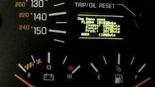
With the memory erased, now a new firmware can be installed. First hit "b". IMPORTANT: DO NOT PRESS ANY OTHER KEYS! Now, use your terminal program to upload a text file (see your terminal program's help file for information on how to do this). Navigate to the firmware file you want to install - it should have the extension ".S19". Make sure your terminal program's file select box does not only look for "*.TXT"-files! While the firmware is being flashed, the terminal program will show the programming progress. The progress bar on the TFT/OLED display will display which portions of memory are being written. The DashComputer has 240K of memory, and the firmware will only use a fraction of it, so don't be alarmed. The TFT/OLED display will look something like this:
If the firmware consists of multiple parts (e.g. firmware, background and splashscreen) wait for the completion of each part, then hit 'b' again and upload the next part. Do NOT erase memory between parts, because this would erase what you previously flashed! If you look closely, you can see different parts of the firmware fill different parts of memory.
When the update process is complete, disconnect the bootloader input from ground (if applicable), turn off the ignition, wait a few seconds, then turn on the ignition again. The new firmware should launch now. You may have to reset the clock at this point. If the firmware doesn't start, restart the bootloader and repeat the process. If the update still fails, try to install the most recent firmware that worked with your unit to make sure the problem is not caused by a bad firmware file.
Using Android
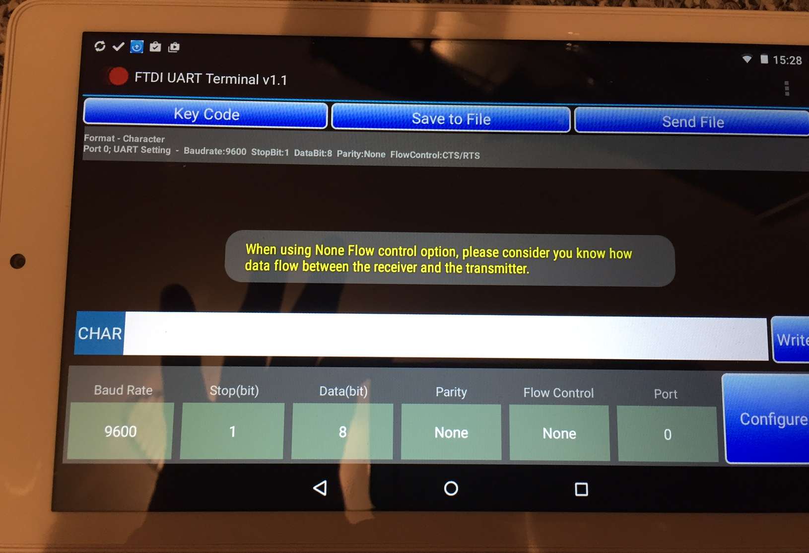
If you own an Android device, there's good news: you can use it to install firmware, and it's pretty simple. You need an OTG-Cable to allow your Android device to act as a host, which you then connect to the DashComputer like you would a PC or laptop. You also need to download a serial port tool for FTDI devices like the free "FTDI UART Terminal v1.1".
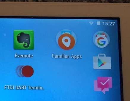
Now, as soon as you connect the tablet or phone to the DashComputer you will be asked some questions like whether or not you'd like to always start the FTDI app each time this device is connected. You do need to configure the port to "Flow Control: None" as shown in the screenshot, and then you're ready to "talk" to DashComputer with your phone!
You just need to hit "CR" to send a "Carriage Return" key to get the menu. Then type the letter a into the white box marked "CHAR" and hit "Write": the Flash will be erased and the progress bar on the OLED as well as a progress bar in the terminal program will show the progress.
Next you will probably want to install another firmware file or the DashComputer will only show the boot screen from now on. So, download the firmware you want to install e.g. from these pages to your device and then enter "b" and nothing else (!) in the white box marked "CHAR" and hit "Write". Nothing will happen! Next, tap "Send File" on the top and select the Firmware file you would like to upload. Upload will start immediately, and if you did everything correctly, you will see a progress bar in the terminal app, and the boot screen will show which portions of memory are being written. If all goes well you can go back to the menu if you tap "CR" after download is finished.
Note: The FTDI app is not the greatest terminal program ever, I find e.g. Hyperterm much easier to use, and that alone says a lot. I've seen the app crash to the point that I had to erase it, reboot and reinstall it. But it does basically work and it's very convenient being able to install firmware like this. Even if something does go wrong, you can never blow the bootloader, so you can always go back and erase/flash the firmware again, or worst case do a firmware install from a PC.
Depending on your firmware, a lot of DashComputer settings are configurable, including km/miles, Fahrenheit/Celsius, etc. The whole set of user selectable settings is called a "configuration". The default configuration contains settings which are suitable for the majority of users. Using the configuration tool you can create a configuration file to download. This configuration can be programmed into DashComputer using the SetOdometer tool, and like the odometer the configuration settings are retained even if you flash a new firmware. The configuration tool doesn't allow selection of out-of-range values.
Here are some of the things the configuration tool lets you configure. In the top left corner the config tool displays the config file format version. Currently this is 1.0, in the future there may be other versions which may or may not be compatible with previous versions.
General options
The VIN field lets you store some relevant information of the vehicle the unit is installed in. Each of the data fields is a single digit. VIN digit 4 is the platform of the car (e.g. "F" for F-body, "P" for Fieros, etc.). VIN digit 8 is the engine code (e.g. "9" for a V6 Fiero 2.8 engine), and VIN digit 10 is the build year of the vehicle.
The next area lets you select the general area the vehicle is in, either North America or Europe/Middle East/Asia.
The flags area lets you select different display options, e.g. if the first mark is checked, temperature is displayed in Fahrenheit. If it is not checked, it is displayed in Celsius. Similarly, distances can be displayed in miles or km, a 12 or 24 hour clock, or 2000 or 4000 pulse per mile VSS input.
Display options
The next section sets different display options. The maximum brightness can be set for day and night mode (the latter requires the IP illumination input to be connected). The brighter the display is set, the lower the lifetime and the higher the potential burn in. A lower contrast setting can extend the lifetime of the OLED considerably.
The splash duration is the number of seconds the splash screen is shown after power up. The screen update determines, how often the speed display is updated. Shorter times make the display more responsive but also more nervous. Similarly the compass updates determines how often the compass input is read and updated.
The speed filter threshold is the speed (either in km/h or mph depending on your preferences) under which the speed display is displayed directly and not averaged. Averaged speed makes for a smooth reading while unaveraged speed is more responsive.
The font color is the color of all characters drawn on the display. Usually this is white. Finally, if the display ages and the display no longer seems to display white as white, you can twist the color offsets of the red, green and blue components slightly using these values.
GPS options
The GPS options allow adaptation of the unit to different GPS receivers with an RS232 output. The baudrate can be set, as well as the timezone offset to GMT. The polarity of the RS232 input can be inverted, e.g. if the receiver used has an inverted TTL output. Currently the unit only processes NMEA GGA and RMC messages, but in the future more messages may be supported. Finally, the number of satellites received and sat lock (icon color red/green) are only displayed for a configurable number of seconds after lock acquisition.
Misc options
This section contains various unrelated settings. The unit sounds an audible beep if outside temperature falls below the "Ice warning" temperature. The short key time is the amount of time required before a short keypress is detected as such. Similarly the long key time is the amount of time for a long keypress. The CAN baudrate can be set as required by the vehicle's CAN bus. And finally the day/night threshold can be set for the illumination input.
Fuel settings
The fuel settings section is specific to the Pontiac Fiero with engine code 9 and 1227170 ECM, for all others this section is "don't care". The "low fuel" setting determines after how many liters of fuel (in 0.1 increments) a low fuel warning should be shown and a warning beep issued. The pulses per 0.05 liter can be adjusted to calibrate the unit to a specific vehicle more more accurate readings. The best possible accuracy is within +/- 1 liter though, which is about 3%. The remaining two values are only displayed for information and not user adjustable at this time.
Window positions
The final section contains the coordinates of various user interface elements. Each consists of a coordinate of the top left corner and the alignment of the text inside the window. Playing with these too much can really mess up the screen, so these values should only be changed with caution.
The DashComputer's odometer is set to 0 for a new unit. But since the DashComputer will usually be installed into a used vehicle, the first thing that is required is to set the unit's odometer to the correct value. Start by noting the current mileage of your vehicle.
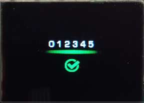
Now download the special odometer firmware available here and flash it into DashComputer as described in the Bootloader section. Turn your ignition off and then on. The DashComputer screen should look like this:
Now, reconnect your terminal program via USB (the USB device gets disconnected with ignition off, so you need to reopen the connection in your terminal program) and hit Enter. The terminal program will ask you to enter the current mileage of your car. Enter the mileage and hit enter. The program will ask you "are you sure?", then hit the 'y' key. The DashComputer should beep and the screen should look like this:
The mileage is now programmed into DashComputer! By the way, since DashComputer's odometer is installed in addition to the existing odometer, you keep the legally required odometer of your car. Even if you remove the odometer LED display (Firebird/Camaro), the odometer is still recorded by the cluster, so if you sell your vehicle you can hook up the LED display again and show the next owner the real odometer.
Setting the configuration
Flashing a configuration is simple: when prompted to enter or update the mileage, hit the escape key in the terminal program. You will now be prompted to upload a new configuration file. The configuration tool generates configuration files with the ".S19" extension, just like the firmware files. Now upload the configuration file using the text upload of your terminal program. The configuration files are really small, so loading the config takes under a second. The program will inform you about success or failure of the upload.
What to do next
After setting the odometer and possibly uploading your configuration you may now proceed to flash the firmware of your choice. The odometer and configuration are preserved across firmware updates, so you'll never have to use this procedure again, unless you move the unit to a new vehicle or would like to update a configuration setting.
Please note: DashComputer's startup splash and background screens are still customized using firmware, so be sure to flash the correct screens into DashComputer that fit the odometer/configuration you programmed!
A word of caution
Okay, first of all, a word of caution: The TFT and OLED displays are a bit delicate. The display is mounted to a rigid PCB etc, but be careful because it's made of glass. I don't know how much abuse it would take, I haven't tried! The display glass is connected to the board with an orange flexible circuit board. On that flex board is a rectangular chip, which is the display controller. Again, I don't know how robust that one is, so I try to stay away from it.
If you just handle the display unit by the sides and not the bottom side with the flex board, you'll be fine. For this reason I also recommend not to remove the little connector with the red wires from the display side, but only from the harness side (which is the way it was delivered). Also, there's a protective film on the display, I suggest keeping that one on the display for as long as possible to keep fingerprints and dirt away from the display surface.
Getting started
The following is the basic "getting started" procedure for the universal (i.e. non-Fiero) version of this project. If at some point you don't get the expected result, STOP what you're doing and contact me, don't start trying things as you might damage something. This description will only contain the ideal case without problems, because I'd rather deal with these unlikely cases if they happen at all and not confuse you and write a lengthy novel of irrelevant troubleshooting of what might happen. With those cautionary words of advice out of the way, please start by testing if everything survived transport. Carefully plug the display's tiny red harness into the small circuit board at the end of the main harness. It only fits in one direction. Next, plug the blue connector into the ECU. DON'T push it all the way in, the terminals are new and very tight, and we just want to run a short test. Gently push it in until you feel resistance, don't push it all the way in. (If you do, you can still wiggle the connector out again later, but why bother). With everything connected, hook up a 12 V power source like a car battery (8-16 Volts is fine) to the supplied red and black wires (black is ground, red is plus). Wait 2-3 seconds, and you should see the display come to life: a white frame around the outer edge (this is the maximum display area) with two gears in the middle. Watch out for dead pixels around the edge, they would be a sign of dead rows or dead columns during transport.
Hook up USB
If this initial test passed, hook up a USB cable to your PC with the ECU powered on. Windows should automatically load a virtual COM port driver. If it doesn't, the driver is available at the FTDI-Website (FT232 driver). Start a terminal program like Hyperterm, and open a connection to the new virtual COM port at 9600 Baud, 8N1, no flow control. Then hit enter. The Terminal program will show a menu including the version number of the bootloader and the serial number of the ECU. If you hit 'a' you can erase the entire flash memory. You will see a progress bar appear and disappear. At this point the unit has passed all necessary initial tests and is functional. You have two choices how to proceed now: configure your unit and install it later, or install it now and configure it later. Go back to the relevant sections and reread for detailed descriptions of configuration and installation
One-time configuration
I would start by configuring the unit right away and use the bootloader to install the "Set Mileage/Configuration" Firmware. Hit 'b' in the terminal program, and send the firmware as Text (!) file / ASCII file. The terminal screen will show progress, and the display will show which parts of memory are written. Once the new firmware is installed, power cycle the ECU. The display will now show a "set mileage" screen. You need to reconnect the terminal program now, since Windows loses the USB-connection every time you power cycle. In the "Set Mileage" firmware you can set your current mileage by hitting enter and then entering your mileage. This mileage is kept in a separate memory and survives all firmware updates! The firmware will ask you "are you sure?", and if you hit 'y', the firmware is stored. You can additionally use this firmware to store a configuration file containing preferences like km/miles, etc. This configuration file is generated with a Windows tool (download on the website). The config file is really small, only a few lines of text. In the terminal program hit escape and when prompted upload the config file like you would a firmware using the upload text/ASCII from your terminal program.
Prepare for the installation
Now you need to get back to the bootloader, but for this you need to complete the harness, so it's now time for installation. So, start by removing the blue connector from the ECU, and you will need to separate the small connector so you're able to install it into the instrument cluster. To separate the small connector again, hold the little board with thumb and index finger of your left hand, and hold all 9 (!) tiny red wires of the display harness with your right hand, and gently pull the connector halves apart again. You can also use a tiny screwdriver, but I haven't had a problem using this method. Next, remove the blue and grey locks from the blue connector with a screwdriver, and you can then remove the black and red wires with their terminals from the connector, you don't need a terminal lock tool for this, the black and red wires were only there for this initial test. Now you're ready to do the electrical installation of the unit in your car. The pinout of the connector is described earlier in this article along with the installation instructions. Basically, select a suitable location for the ECU (e.g. in an F-body near the center console), and splice into the proper circuits of your car. A factory service manual is really helpful here. Use the supplied terminal contacts and a good crimp tool. Additional terminals are readily available in the internet or at auto parts stores. The minimum 10 connections you will need to hook up are: Ignition power and ground (pink and black) Illumination input (grey) Boot switch input (black/white) "Trip reset" and "Set clock/menu" pushbutton inputs (black/white) and ground (black) Outside temperature input and ground (green/white and black) VSS input (brown or dark green/white) But again, if at some point you're unsure, stop and get in touch with me before you make a mistake and possibly damage something...
Here are the download files for this project. The top section is a list of available firmwares for the generic version (i.e. currently F-bodies), next are the Fiero specific firmwares.
Finally, there is the "Set odometer and configuration" firmware, a tool that helps you merge firmware+splashscreen+background into a single download file and an accompanying Windows download to generate your configuration using the config editor.
Firmware files
 |
|
|
Splash Screens
 |
 |
 |
 |
 |
 |
 |
 |
 |
 |
US Backgrounds
 |
 |
 |
 |
 |
 |
Metric Backgrounds
 |
 |
 |
 |
 |
 |
Tools
|
Download File Merger "SRecord (srec_cat.exe)" |
|
Configuration editor for Windows V1.02 |